For optical communication, testing the optical power is an essential step in building the optical environment. The level of optical power affects the performance of the receiving device. Too low light power will make the device impossible to identify, and too high light power will damage the device itself. Therefore, we should pay attention to the detection of optical power.
To detect the optical power, we need to use the optical power meter. Before detecting the optical power of the device to be tested, we must first ensure that the optical power meter is normal. If the display value of the optical power meter is wrong, we need to calibrate it and let the optical power meter point to the correct value. For this reason, we also need a standard light source.
The following editor will introduce the steps to calibrate the optical power meter:
Let's start by clarifying the logical idea. The ultimate goal is to get a standard light source, we knew the optical power value of the standard light source, and then connect the light to the optical power meter, adjust the display value of the optical power meter, so that it is equal to the actual optical power value we know. Well, then the purpose is to need a light source that knows the true optical power value.
We use the standard light source of HP devices, and then use the standard optical power meter inside the device (of course, there may be readers at this time, if your device is also inaccurate? First of all, you should clear the degree of corresponding represents the specific value is the international community human consensus, this is a standard, and then you think I am using the device is not allowed that take a few device light source to test, if you have been finding the most accurate the device is only the human used to make standards, this is meaningless, please don't drill), To read the value of the optical power emitted by the optical port of the device, a light source that knows the true optical power value can be obtained.
Here are the specific operation steps.
1. Set up a standard light source
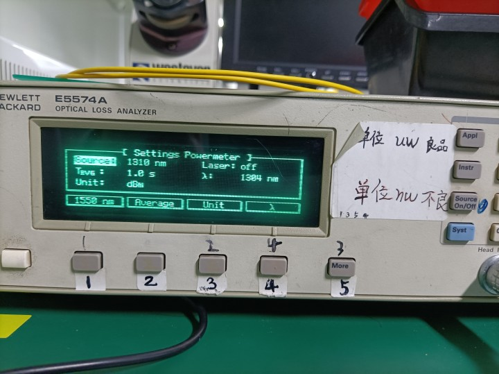
After the boot to the following interface.
Press the "1" button (select Setting) to enter the following interface.

The "1" button in the figure above corresponds to the central wavelength of the light source, with two choices: 1310nm and 1550nm;
"2" button corresponding to the time, editor also do not understand the specific meaning , should be the frequency of light;
The "3" button corresponds to the unit, you can choose dBm or W ;
The "4" button corresponds to a wavelength, and the value of the wavelength can be changed by inputting a number, which is the central wavelength received by the device.
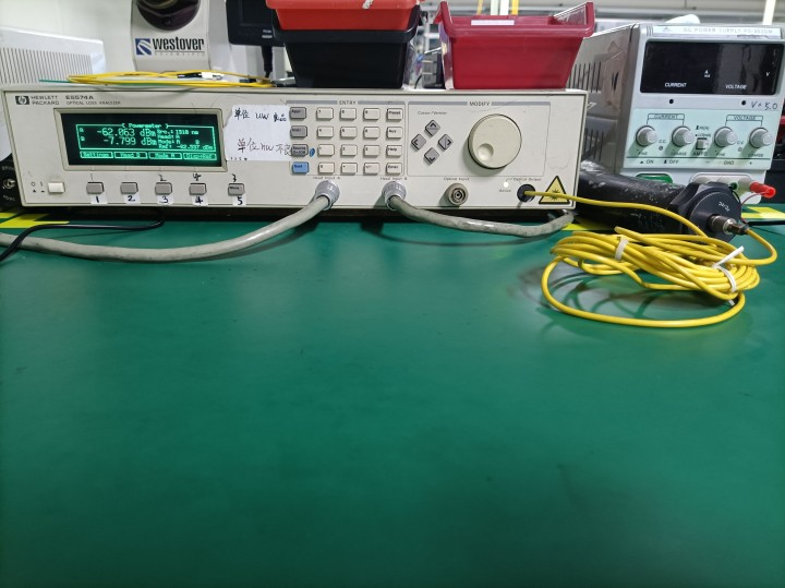
Click the "instr" button to return to the Power Meter interface, which is the first picture. Click the "Source On / off" button to open the light source output. The output light of the device is connected to the receiving position of the device, as shown in the figure below, and the optical power value of the current standard light source is-7.799 dBm.

2. Adjust the optical power meter
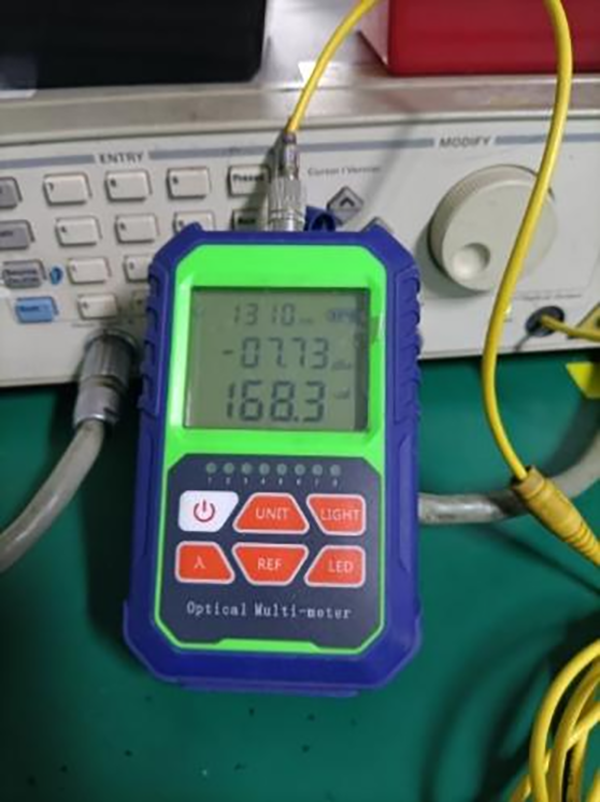
Transfer the output light to our optical power meter, as shown in the figure below.

Take my optical power meter as an example, first select the corresponding wavelength. Since the light source is 1310nm, select 1310 here, Press "λ", "UNIT" and "REF" to enter the adjustment mode at the same time, and click "UNIT" and "REF" to adjust the amplitude up and down to -7.79dBm. Click the on/off button in the upper left corner of the power meter to exit the debugging mode.
To this our light power meter adjustment is completed.The above is the knowledge explanation of optical power meter calibration provided by Shenzhen HDV Phoelectron Technology Co., LTD. Thank you for watching,About our company's related network products and equipment, covering ONU series, OLT series, transceivers, SFP modules, SFF modules and so on. welcome everyone to understand, See you next time


